Flow in Conduits
A.J. Erickson, J.S. Gulliver, R.M. Hozalski, O. Mohseni, J.L. Nieber, B.N. Wilson, P.T. Weiss
Conduits can transport two types of flow: pressurized conduit flow and open channel conduit flow. Pressurized conduit flow is defined as the transport of water in closed conduits (e.g., pipes) that are flowing full. Flow occurs because there is a longitudinal pressure difference along the conduit. Open channel conduit flow is the transport of water by gravity with a free surface open to atmospheric pressure in which the channel determines the size, shape, and slope of the conduit.
Closed Conduit Flow
Stormwater conduits are designed for a specific capacity (i.e., maximum discharge) that depends on the upstream conditions and downstream controls. Conduits flowing full operate at, or near, that capacity. Measuring discharge in a full-flowing conduit with a weir or flume is not recommended because weirs and flumes reduce the capacity of the conduit and the relationship between discharge and the water surface elevation is not well established without a critical depth. Area-velocity probes, however, can measure discharge without causing significant obstruction in conditions that provide adequate depth over the probe. The following are advantages and disadvantages to using probes to measure full-flowing conduit discharge in lieu of weirs or flumes:
Advantages:
- Probes create less flow obstruction than weirs or flumes
- Probes can accurately measure depth or discharge in full-flowing conditions
- Probes are usually easier to install
Disadvantages:
- Probes cannot accurately measure small discharge associated with small storm events or the entire rising and falling limbs of hydrographs
- Probes sometimes require calibration, which may be difficult for certain site conditions
- Probes require additional cost and maintenance
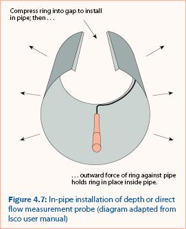
A discharge measurement probe is usually attached to a flexible metal ring, which, when compressed, can be slid into the conduit to the desired location (figure 4.7). When the compression is released, the ring expands against the inside of the conduit where friction holds the ring and probe in place. The probe is connected to a data logger that records such information as depth and velocity, which is then converted to a cross-sectional area of discharge, and then to a measurement of discharge. Additional equipment, such as tipping bucket rain gages, can be connected to the data logger, as well.
Area-velocity probes must be located at the bottom of the conduit and oriented so they face the oncoming discharge directly. They also require a minimum water depth (usually 1 to 2 inches, ~2.5 to 5 cm) in order to obtain accurate measurements. Stormwater pipe systems can have supercritical flow which produces large discharge values with minimal water depth. Significant errors can occur when using probes to measure these discharge conditions when the depth does not exceed the minimum suggested by the manufacturer.
Two common brands of area-velocity probes used at the time of publication are Isco (figure 4.8) and Campbell Scientific. Campbell Scientific produces a velocity sensor that must be combined with a depth measurement and area conversion computation to estimate discharge. Campbell Scientific equipment is capable of connecting with equipment from other manufacturers but requires computer code written by the user to communicate with the equipment. Isco equipment does not require code but it cannot be used in combination with equipment from other manufacturers. Most discharge measurement probes require connection to a data logger to record measurements with respect to time.
Area-velocity probes should be used only when an insignificant portion of the runoff event will occur at depths below those required for accurate measurements. Otherwise, a large portion of the total runoff volume may not be measured accurately.
Partially full conduits
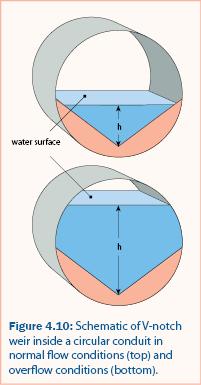
Conduits flowing partially full are a specific instance of open channel flow in which the channel is simply the size, shape, and slope of the conduit. Therefore, a V-notch compound weir (figure 4.4), a circular weir (Addison 1941, figure 4.9), or a V-notch weir (figure 4.10) may be used to measure the discharge. To ensure accurate discharge measurements in a conduit with a weir, the weirs and probes must receive regular inspection and maintenance to remain free of sediment and debris that may accumulate behind the probe or weir.
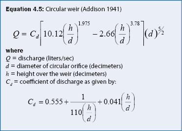
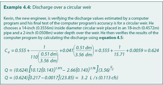
All weirs should be constructed so that the bottom of the weir fits the contour of the conduit and can be sealed with a waterproof sealer such as polyurethane. If a circular weir is to be used in a non-circular conduit, it is important that the crest of the weir remains circular (unless a calibration curve is determined for a specialized weir). For a circular weir, depth can be converted to an estimated discharge using equation 4.5. Example 4.4 demonstrates the use of equation 4.5 for discharge estimation using a circular weir.
A V-notch weir may be used as an alternative to a circular weir for partially full conduit flow, as shown schematically in figure 4.10. For normal flow conditions, discharge can be estimated by equation 4.3, which applies to any V-notch weir section. Note that overflow conditions shown in figure 4.10 will not be estimated accurately by either V-notch (equation 4.3) or compound (equation 4.4) weir equations. A calibration to the specific conditions is required.
When measuring open channel discharge in a conduit, a Palmer-Bowlus (figure 4.3) flume may be used as an alternative to a weir. A Palmer-Bowlus flume is a Parshall flume modified to fit inside a circular conduit. Commonly available sizes range from 4 inches to 72 inches (10.16–182.88 cm) in increments similar to those of commercially available pipes. Palmer-Bowlus flumes tend to collect less debris compared to weirs because they produce less obstruction to the flow through the conduit. Manufacturer specifications should provide calibration or rating curves along with installation instructions for depth-measurement equipment.
Recommendations
For conduits with small-discharge (i.e., not sufficient to provide adequate depth over a probe), it is recommended that a weir be used for discharge measurement. Circular weirs provide a good combination of small-discharge accuracy and large-discharge capacity and are recommended for open channel conduit flow when there is adequate capacity to pass the design flow. The combination of a circular weir and a pressure sensor has proven to be effective for conduit flow over a wide range of discharges. The pressure measurement can be used to indicate depth over the weir. Pressure sensors in combination with circular weirs in large-discharge conditions (nearly full-flowing conduit) may require an individual calibration.
If a pressure sensor is to be used in conjunction with a weir, it is important to remember that a minimum depth above the probe is typically required to obtain accurate measurements. It is recommended that the weir height be set to achieve this minimum depth or more.
Continue to Infiltration.