Open Channel Flow
A.J. Erickson, J.S. Gulliver, R.M. Hozalski, O. Mohseni, J.L. Nieber, B.N. Wilson, P.T. Weiss
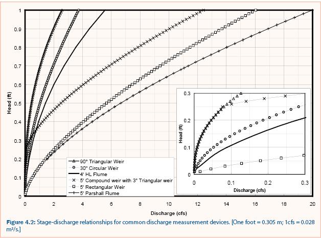
Open channel flow transports water by gravity with a free surface exposed to the atmosphere. Any of the principal methods of discharge measurement outlined below can be used to measure open channel flow. Some methods are more accurate than others while some methods measure a large range of discharge. Stormwater is variable and thus the method for measuring stormwater discharge must be able to measure small values of discharge accurately while also having the capacity to measure large values of discharge. For reference, the depth-discharge (also called the stage-discharge) relationship for six discharge measurement techniques is shown in figure 4.2.
It is important to understand the concepts of steady and unsteady flow because the methods for estimating discharge in open channels for steady and unsteady flow are different. For flow to be considered steady, all flow properties (velocity, depth, etc.) must remain constant with respect to time. For example, large open channel flow (e.g., large rivers) can be approximated as steady flow for time periods in which the flow changes are not significant. The principal methods of discharge measurement described below assume steady flow conditions, but in most natural systems, steady flow is only present for short time periods.
To analyze unsteady flow using steady flow concepts, flow data must be collected near-continuously over small time steps. If the time step is small, the flow can be considered steady for that time step and the total volume of flow can be estimated by multiplying the discharge (volume per time) by the time step duration (time) for each data point and summing the products for an entire event (or day, month, year, etc.).

The principal methods to estimate discharge for steady flow are as follows:
- Continuity (Flow rate (Q) = Velocity (V) multiplied by Area (A)): The average (or area-weighted) flow velocity can be multiplied by the cross-sectional flow area to estimate the discharge.
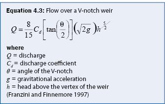
- Weirs (e.g., V-notch, rectangular, circular, compound): As fluid passes over a weir, it transitions through critical flow (Froude number = 1) to super-critical (Froude number > 1). Discharge at critical flow is solely dependent on the cross section. Discharge can be estimated accurately under critical flow conditions using the depth of water behind the weir and equations corresponding to the type of weir used.
- Flumes (e.g., Parshall, Palmer-Bowlus, see figure 4.3): Discharge measurement flumes produce a constriction in the flow and thus cause the flow to transition to critical flow (Froude number = 1). Similar to weirs, a measurement of the depth of critical flow and relevant flume dimensions can be used to estimate the discharge through the flume.
- Discharge measurement probes (e.g., area-velocity probe, sometimes called area-velocity meter or area-velocity sensor; current meters): Area-velocity (AV) meters use sonic waves to measure the discharge velocity throughout the flow cross-section. The velocity values are multiplied by the corresponding cross-sectional area and summed to estimate the total discharge. To ensure accuracy, area-velocity meters require a minimum water depth over the probe as specified by the manufacturer. Most meters do not correctly integrate negative (i.e., flowing upstream) velocities that may occur as a result of turbulence in a backwater profile. Therefore, these meters can produce erroneous data during small-discharge conditions and in situations with downstream obstructions in the flow (such as a weir or debris) that may cause negative velocities. Current meters measure velocity at a point in the flow that represents a portion (i.e., area) of the flow cross section. Discharge is then computed from continuity (Q = Σ (V x A) and related to a stage discharge relationship (i.e., rating curve). For more information on current meters, refer to Chapter 10 of “Water Measurement Manual” (U.S. Bureau of Reclamation 2001).
- Backwater (water surface) Profiles: Backwater profiles for gradually varied flow use discharge, channel geometry, conservation of energy, and estimates of friction losses (usually based on Manning’s Equation) to calculate the water surface elevation in the channel as a function of distance from a channel location of known depth. When used to estimate discharge, the water depth is measured at some distance from a control (such as weir or free outfall) and other variables are either calculated or measured. Backwater profile calculations are iterative and are performed with a guessed value of discharge that is adjusted until the calculated depth at the known distance from the control matches the measured depth. For a more complete explanation with examples of backwater profile calculations, see an open channel flow text or manual, (e.g., Sturm 2001).
- Manning’s Equation: Robert Manning developed Manning’s equation (equation 4.2) in the 19th century to estimate discharge for uniform open channel flow using cross-sectional area, hydraulic radius, energy grade-line slope, and an empirically defined roughness coefficient (n) (Sturm 2001). The potential measurement uncertainty in roughness coefficient, however, is large, and it is recommended that Manning’s equation be used only as a last resort to estimate discharge in stormwater applications.
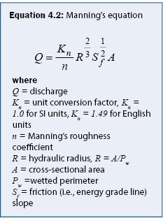
Two components of Manning’s formula make it potentially inaccurate when estimating stormwater discharge. First, the slope of the channel bed (or pipe) is often assumed to approximate the energy grade line; second, the empirically defined roughness coefficient is often estimated from a table of values. For long channels of constant slope, one can often assume that the channel slope approximates the energy grade line, but short channels, transitions, and changes in the flow, which are common in stormwater systems, invalidate this assumption. Additionally, measurement uncertainty is large for short channels of shallow slopes because of human and instrument error. The empirically defined roughness coefficient often must be calibrated for a specific system and the potential measurement uncertainty is large. It is recommended that Manning’s equation be used only as a last resort to estimate discharge in stormwater applications.
Selection of a discharge measurement method is dependent on many factors, including accuracy, cost, range of discharge, and site conditions. For further discussion of individual factors, see Chapter 4 in the “Water Measurement Manual” (U.S. Bureau of Reclamation 2001).
All the discharge measurement principles listed above require a measurement of water depth and a known channel (or pipe, etc.) geometry to calculate discharge. In the case of a weir, the water depth is measured behind the weir and weir equations (discussed in detail below) convert depth to an estimated discharge over the weir. In the case of discharge measurement probes, a water depth is needed to determine the wetted perimeter. The principal methods of depth measurement use pressure under hydrostatic conditions and density. Bubbler probes and pressure transducers, when located under the water surface, measure the pressure of water (i.e., hydrostatic pressure), which corresponds to a specific depth of water. Ultrasonic and Doppler probes, typically positioned above the water surface, locate the water surface using the change in density from air to water because the water surface reflects the acoustic signal back to the probe.
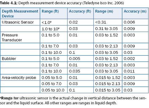
The accuracy of any depth measurement should be verified prior to installation of equipment and re-verified each time the site is visited to ensure that the equipment is calibrated correctly and in good working condition. A graduated ruler (i.e., staff gauge) affixed to a non-moving structure (such as the weir or a post) can be used to verify the depth visually. If the depth measured by the staff gauge does not correspond with that of the depth measurement device (e.g., bubbler), verify that the staff gauge has not been disturbed and that the depth measurement device is working properly. Most manufacturers provide documentation that describes measurement range and accuracy for their respective depth-measurement devices. For example, Isco (Teledyne Isco Inc. 2006) reports the measurement accuracy for the Isco 4200 discharge meters as shown in table 4.1.
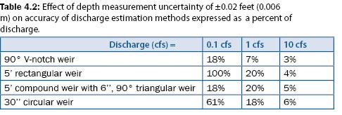
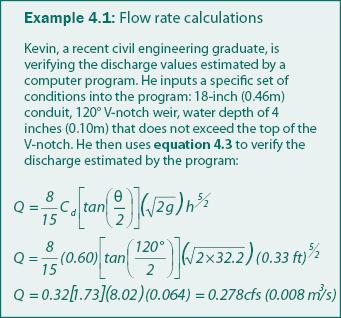
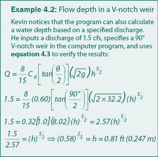
V-notch weirs measure small discharge accurately (± 1 to 2%, A.S.T.M. 2003) because small changes in discharge result in large changes in depth. Therefore, measurement uncertainty associated with the depth measurement has little effect on the estimated discharge. For example, a measurement uncertainty of ± 0.02 ft (0.006 m) in a 90° triangular weir with a discharge of 0.1, 1.0, and 10 cfs results in a discharge accuracy of ± 18%, ± 7%, and ± 3%, respectively, as shown in table 4.2. The discharge equation for triangular weirs is given in equation 4.3. Examples 4.1 and 4.2 are provided to show how equation 4.3 is applied in two different situations. The discharge coefficient (Cd) as shown in equation 4.3 varies from 0.58 to 0.62, is dependent on θ and h, and may be determined graphically or experimentally. However, a value of 0.60 may be assumed with a measurement uncertainty of ± 3%.
90° V-notch weirs, however, are limited because large discharge requires more depth as compared to other weirs and flumes for the same discharge. For example, a 90° V-notch weir requires 0.9 ft of depth to measure 2 cfs whereas a 30-inch circular weir requires less than 0.3 feet of depth, a Parshall flume requires less than 0.25 feet of depth, and a 5-foot rectangular weir requires less than 0.05 feet of depth, as shown in figure 4.2. Rectangular weirs require less depth for the same discharge than all the other measurement devices shown in figure 4.2. Rectangular weirs, however, do not accurately measure small discharge because small changes in depth result in large changes in discharge. Therefore, measurement errors associated with the depth measurement have a significant effect on the discharge estimation as shown in table 4.2. As mentioned above, the optimal method for measuring stormwater discharge must be able to measure small discharge accurately while also having the capacity to measure large discharge.
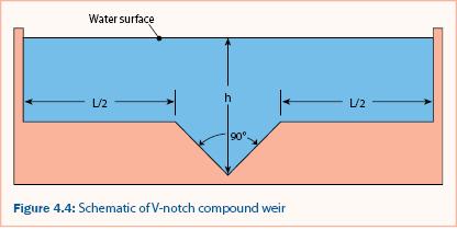
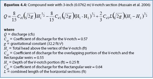
A compound weir and circular weir (Addison 1941) both measure small discharge while also having the capacity to measure large discharge. As shown in table 4.2 and figure 4.2, the compound weir composed of a 3-inch 90° V-notch section and a 5-foot rectangular section (see figure 4.4) measures small discharge as accurately as a 90° V-notch weir but also measures large discharge without large head requirements (e.g., 14 cfs with less than 1.0 ft of head over the weir).
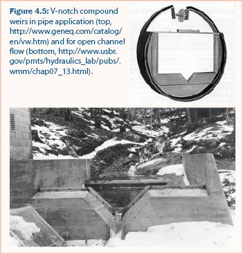
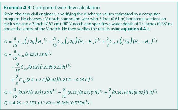
A schematic of a V-notch compound weir is shown in figure 4.4, and two applications are shown in figure 4.5. Using the water surface elevation and the weir dimensions, equation 4.4 can be used to estimate the discharge for a 90° V-notch compound weir, as performed in example 4.3. A circular weir also measures both small and large discharge but is less accurate at large discharge than the other methods listed in table 4.2.
When using a weir to estimate discharge, it is very important to ensure that all flow enters by traveling over the weir and not around the weir or under the weir. It must also be noted that:
- The weir (or some other barrier) should be extended into the ground (sometimes three or more feet) to minimize groundwater seepage under the weir.
- To ensure critical flow over the crest of the weir, it is important to maintain a “free outfall” over the weir. As long as the flow conditions downstream of the weir do not affect the flow over the weir, a free outfall is maintained.
- Weirs will back up the flow in the channel or conduit, which may alter the locations of flow entrance or exit for the stormwater treatment practice.
- The weir itself requires inspection and any necessary maintenance at least once a month to ensure that water does not leak or scour under the weir, that it is free of debris that may collect on the upstream side and disturb the water surface, and that it is in proper, working condition.
A Parshall flume (Parshall 1936) may also be used to estimate discharge in open channels. Parshall flumes are rectangular sections that constrict the flow to create critical flow through a specific section of the flume. The discharge may be estimated by measuring the water surface elevation just upstream of the critical section and converting it to discharge using a calibration curve, which is most often provided by the manufacturer. Parshall flumes are readily available in widths from 2 inches to 120 inches (5.08–304.8 cm).
H, HS, and HL flumes (Gwinn and Parsons 1976) combine the sediment movement capabilities of a flume with the accuracy of a weir. The cross-section of H flumes, which is initially rectangular, converges at the downstream end with the top side walls sloped downward as is shown in figure 4.6.
There are three types of H flumes categorized by size: the smallest size is the HS flume, the intermediate is the H flume, and the largest is the HL flume. Many manufacturers sell pre-constructed H flumes with rating curves that provide the relationship between water level and discharge with ranges from 0.085 cfs for HS flumes to 117 cfs for HL flumes (0.002 m3/s–3.313 m3/s, respectively).
Compared to weirs, flumes are different in the following ways:
- Flumes do not create a pool upstream of the flume,
- Flumes are less prone to collecting debris,
- Flumes obstruct the movement of sediment less than weirs,
- Flumes require more space and effort to install,
- There is, in general, a smaller measurement range of discharge when using a flume as compared to a weir in the equivalent space.
Recommendations
Open channel flow in stormwater applications is most often unsteady and the discharge magnitude is often varied. Compound weirs, as shown in figure 4.2, provide a combination of accurate small discharge estimation and capacity to measure large discharge; therefore, it is recommended that compound weirs be used whenever possible. In channels with a large sediment load, weirs may create excessive deposition that will eventually affect the accuracy of the weir. In such cases, a properly sized H-flume (open channel flow) or Parshall flume may be used to measure open-channel flow.
Continue to Flow in Conduits.