J.L. Nieber, A.J. Erickson, P.T. Weiss, J.S. Gulliver, R.M. Hozalski
For synthetic runoff testing (level 3) the infiltration practice is filled with water as a simulation of a natural runoff event. Careful planning is required for this approach because the volume of water required to fill the stormwater treatment practice can be significant and might far exceed the capacity of the nearby fire hydrant or available tanker trucks. Assuming that a sufficient water supply is available, the procedures for performing synthetic runoff testing on several infiltration stormwater treatment practices are described in the following.
Infiltration basins
To conduct a synthetic runoff test of the infiltration capacity of an infiltration basin, the basin is filled with water and the rate that the water infiltrates is estimated based on the rate of drop of the water surface. If the volume of water required to fill the basin is significantly more than is available, then it is possible to delay the experiment until an actual runoff event of sufficient magnitude fills the basin.
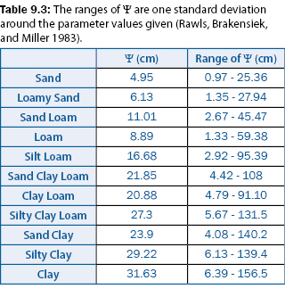
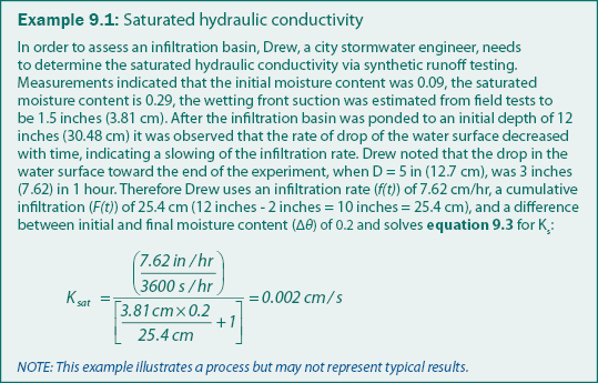
The saturated hydraulic conductivity of soil an be approximated from equation 9.3 where the infiltration rate f(t) is the rate at or near the end of the experiment. Values for the wetting front suction for different types of soil is given in table 9.3. An example calculation if provided in example 9.1.

Infiltration trenches
For infiltration trenches, synthetic runoff testing is conducted by applying synthetic stormwater such that infiltration into the trench is initiated. This could be by filling any water storage area with water or by applying synthetic runoff to a clean area directly upstream of the trench. The water surface should be brought to at least 1 foot (0.305 meters) above the surface of the trench to provide enough height for the measurement of water level drop during infiltration.
Conducting a synthetic runoff test for a trench requires planning because the volume of water required for the test can be significant and depends on the volume-elevation characteristics of the depression. A depression with steeper side-slopes will require less water than a depression with less steep sides. While the soil surrounding the trench will also facilitate some infiltration, infiltration trenches are used in areas where the surface soil has very minimal infiltration capacity, and therefore it is generally valid to neglect this additional infiltration capacity.
To determine the hydraulic conductivity of the trench, the drop of the ponded water surface is tracked over time. Over any given time interval, the volume of water that flows into the trench and the hydraulic conductivity of the trench can be computed with equation 9.4. Again, this method assumes that the outflow from the depression is from the trench alone, and that the flow through the soil surrounding the trench is negligible.

Permeable pavements
Synthetic runoff testing of permeable pavements is feasible if water can be stored on the surface of the permeable pavement to a measurable depth (> 6 inches (15.24 centimeters)) for a length of time necessary to measure the infiltration (> 1 minute). Generally the pavement surface will be planar and sloped on a uniform grade, so curbs or some form of berm around the boundaries of the pavement will be required to store and infiltrate a measurable depth of water. The base layer underlying the permeable pavement is generally very porous, so it is necessary to measure only the saturated hydraulic conductivity of the pavement layer itself. Knowing the thickness of this layer and the rate of drop of the infiltrating ponded water, it is possible to compute the saturated hydraulic conductivity from equation 9.3.
Alternately, water can be applied at a metered rate through a sprinkler onto a specified area of the pavement surface. The sprinkler may be simply a hand-held device, or it may be held in a frame structure. The idea behind the water applicator is to determine the rate of application that causes runoff to occur in the application area. The flow rate through the applicator is increased to the point where runoff just begins to occur. The runoff will be evident by water flowing over the surface to the side of the application area. At the rate of application where runoff just starts to occur, the flow rate should be reduced again until runoff stops. The infiltration capacity is, then, just the rate of water application.
Continue to Monitoring.