
Automatic sampling of water containing suspended solids
O. Mohseni, J.S. Gulliver, and P.T. Weiss.
Research conducted on an ISCO 3700 automatic sampler at the St. Anthony Falls Laboratory has shown that samples collected by automatic samplers do not accurately represent the suspended solids concentration in stormwater runoff (Gettel et al. 2009). A sediment feeder was installed at the upstream end of an 18-inch diameter pipe where sediment and water were fed into the pipe. Suspended solids were sampled 34.8 feet downstream of the feed point. Discharge through the pipe was measured using a v-notch weir downstream of the pipe. The tests were conducted using five sediment size distributions: (1) silts and clays with a median diameter of 25 μm and a maximum diameter of 88 μm, (2) silts of size 44-88 μm, and sands with the size ranges of (3) 125-180 μm, (4) 180-250 μm, and (5) 250-355 μm. Four automatic intake configurations were tested: (1) sampling tube oriented parallel to the flow and facing upstream, (2) sampling tube oriented parallel to the flow and facing downstream, (3) a commercially available intake manifold attached to the end of the sampling tube and to the bottom of the pipe, and (4) a commercially available intake manifold attached to the end of a sampling tube and only the tube attached to the side of the pipe so the manifold was able to move freely in the flow.
The results given in Tables 1 and 2 showed that the automatic sampler over-estimated the concentration of the suspended sediment by up to 6,600% for large particle sizes. Silts and clays are typically sampled more accurately. The configuration in which the manifold was allowed to move freely in the flow gave the most accurate results. For total suspended solid concentration, if the size distribution is not too large, automatic sampling with the manifold free to move laterally will provide concentrations within 25% of the actual. The sampling of large sand particles, however, in this configuration resulted in errors of approximately 200%. This means that size distributions will be skewed towards larger sizes by the use of an automatic sampler.
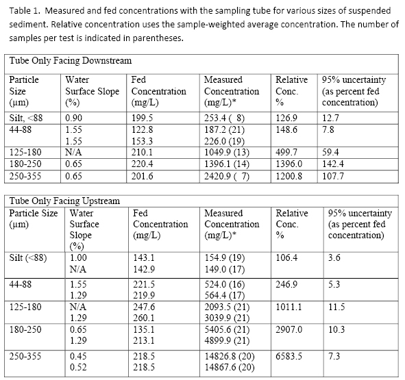
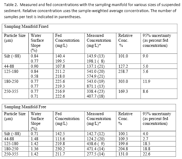
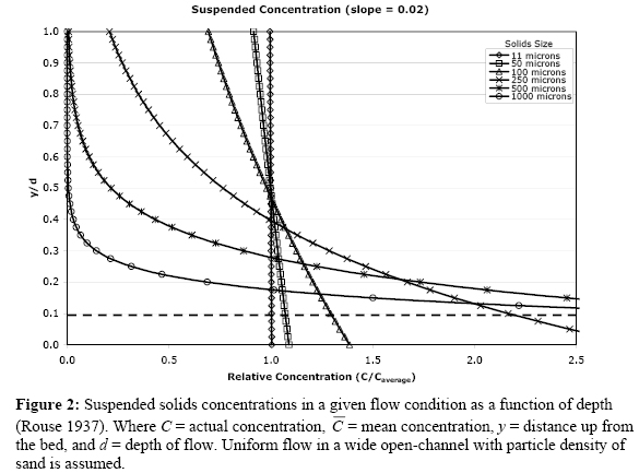
Solids suspension is a function of flow characteristics, and particle size, density and shape. Sampling suspended solids concentration is strongly influenced by the location of the intake within the depth of the flow. For a typical stormwater conduit, concentrations larger than the mean concentration are found at lower relative depths for most particle sizes (>10 μm = micrometers or microns). Intakes of automatic samplers are typically placed at the base of conduits, which can result in suspended solids concentrations containing larger particles being over-estimated.
As depicted by the dotted line in figure 2, if a sampler intake is located at 10% of the total depth (y/d = 0.1), the resulting sampled concentration for 250 μm sand particles will be approximately 2.1 times the mean concentration for the given flow condition. Similarly, at that same relative depth and flow condition, 100 μm fine sand-silt and 11 μm clay particles are sampled at approximate concentrations of 1.3 and 1.0 times the mean concentration, respectively. For this conduit, only clay particles can be sampled accurately. Suggestions have been made to place the sampler intakes at a depth above the bed, but the automatic sampler is unable to capture any events below the intake depth.
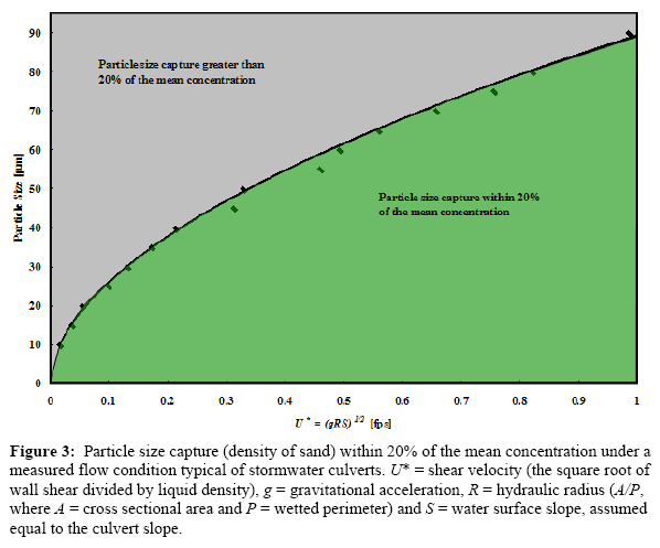
Developed from equations given in Rouse (1937), figure 3 represents a limiting particle size for a measured flow condition to ensure a sample concentration within 20% of the mean. Figure 3 assumes that the flow is fully developed, i.e., does not depend upon upstream entrance conditions. When sampling solids concentrations with automatic samplers, the sample is within 20% of the mean when the maximum particle size is at or below the limiting line depicted in figure 3.
Example 1: Accuracy of automatic sampling of water containing suspended solids.
An 18 inch inside diameter culvert is oriented at a 2% slope and flowing at 6 inches of depth. Determine the solid size of sand density particles that will be captured within 20% of the mean concentration of that particle size. To use figure 3, we need to calculate the shear velocity of the flow, which is the shear stress on the culvert wall divided by the density of stormwater. The hydraulic radius can be found in books on fluid mechanics or calculated at a Web site. In this case R = 0.31 ft. Then,

Then, using figure 3, we can determine that the particles less than or equal to 60 μm in equivalent diameter, i.e., silts and clays, will be measured within 20% of their true mean concentration. Sand-like particles greater than 60 μm, such as fine sand and above, will not be measured within 20% because of their vertical distribution in the flowing stormwater.
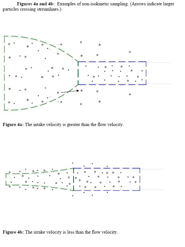
A second challenge is the velocity with which the sample is drawn. Automatic samplers are equipped with pumps to draw samples, which create velocities different from localized streamflow velocities at the intake. When the intake velocity is equal to the streamline velocity (i.e., localized streamflow velocity), the sampled suspended solids concentration equals the mean suspended solids concentration and is referred to as isokinetic sampling. With varying flow velocities and fixed intake velocities, automatic samplers rarely sample isokinetically. Research on non-isokinetic samplers (Federal Interagency Sedimentation Project 1941) found significant errors for particle sizes greater than 60 μm silt. Errors associated with non-isokinetic sampling are due to inertial effects of the particles. The larger particles have a significant mass, which corresponds to inertial forces that can result in particles not following curved flow streamlines coming into a non-isokinetic sampling port. Dividing flow streamlines are indicated in figures 4a and 4b as illustrations of non-isokinetic sampling. Figure 4a is an example of when the intake velocity is greater than the flow velocity. Figure 4b is an example of when the intake velocity is less than the flow velocity. The green dashed line is an initial capture control volume upstream of the intake, and the blue dashed line is the corresponding capture control volume of the intake. Both figures contain two particles sizes, one significantly larger than the other. The small particles have low inertial forces and have less of a tendency to cross streamlines. The larger particles have enough inertia to move in a horizontal direction and can cross the streamlines. For the case in figure 4a, a portion of the larger particles leaves the flow streamlines and is not captured by the intake, resulting in a measured concentration smaller than the true mean. When the flow velocity is greater than the intake velocity, as in figure 4b, the larger particles cross into the streamlines, resulting in a larger measured concentration than the true mean.
For most stormwater conditions, the sampling of fine sand and sand will not be sufficiently accurate. This does create additional challenges in sampling chemicals that are attached to particles, such as particulate phosphorus and many metals and organic chemicals. Currently, the only means of ensuring accurate solids sampling is to capture all of the solids over a known length of time and discharge (Sansalone, et al. 1998). Then, suspended solids concentration may be computed from equation D.1. The units should be equivalent on each side of equation D.1.
where:
C = solids concentration (e.g., mg/L)
M = mass of solids collected (e.g., mg)
t = time of collection (e.g., seconds)
Q = stormwater discharge (e.g., liters per second)
Research is being conducted at the University of Minnesota’s St. Anthony Falls Laboratory to investigate the limits of sampling suspended solids and particulates and to further improve sampling methods for automatic samplers.
References
Federal Interagency Sedimentation Project. 1941. Laboratory investigations of suspended sediment samplers. Iowa City, IA.
Gettel, M., Brand, J., DeGroot, G., Mohseni, O., and J.S. Gulliver. 2009. Accuracy of suspended sediment concentration measurements with automatic samplers. Submitted to the Journal of Drainage and Irrigation Engineering.
Rouse, H. 1937. Modern Conceptions of Mechanics of Fluid Turbulence. Transactions of the ASCE 102:463-543.
Continue to Assessing thermal impacts of stormwater BMPs.